
The left picture is the 10m trap. 3 wnds and at both ends a half wnd. So 4 wnds in total. Resonation at 28.8MHz. Fixed the alu tubs to the PVC tubes with standard M4 bolds. The ends of the trap were solderd to make a ring, and screwed to the pipe with stainless steel screws.
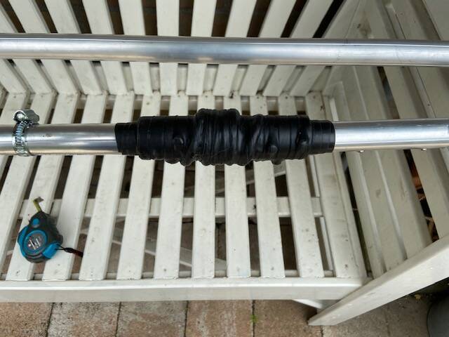
The potential difference between aluminum and stainless steel makes the connections to corrode, but only if there is an electrolite around. So I put rubber tape around it. So it is waterproof for a while at least.
The right picture gives the same image for the 15m trap. I made 5 wnds plus only one half wnd at one end. So I came in the middle of the band in resonation at 21275 kHz. Measuring the resonation frequency has to be done in the free air,.....not laying on the table!! Best is to pick up one end of the trap in your hand, keep it vertical and away from any object with at least 30cm distance.
The easiest way to measure the resonance is to use the good old grid dipper. I don't have one, but I have a antenna analyzer and I did the measurement with it by making one loop of two cm and connected it to the analyzer input. Than do a sweep over 3-30MHz while you keep the 2cm loop close to the trap. Probably you only see a nice curve,.......but where is the resonance ??
Well, make the sweep on the analyzer smaller in the frequency area where you expect the impedance dip caused by the resonance. In my case it was easier to look for a phase change. Measuring the trap without connecting it to the rest of the antenna gave me a nice phase change on the resonance frequency. When the antenna was completely assembled, I couldn't find the dip anymore ??
But no problem, the antenna works OK.